
Discrete Phono Amp + Headphone Amp – Development Log
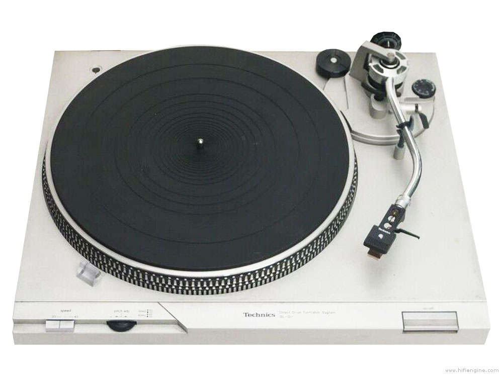
My brother gave me a used turntable (Technics SL-D1) along with a cheap DJ preamp. I didn’t have any vinyl records to play, so he loaned me a few as well. I was once a bit of an audiophile back in the day (early 80’s) but after CD came out I ditched vinyl as a medium of choice because of how cumbersome it was to play. (not to mention the limited dynamic range, etc.)
Having not listened to vinyl for a few decades, I was curious to playback some familiar tunes – and I was surprised as to how clean the sound coming out of the vinyl was – much better than I remembered.
Slowly I started to listen to more vinyl and started feeling the limitation of the phono amp that I was using. So I looked around the Internet for phono preamp circuits, and formulated the idea of designing a discrete transistor phono preamp.
Late 70’s HiFi Phono Preamp
I found a schematic for Sony TA-F6B. The phono preamp section used a differential FET input stage, current mirror, and class-A gain stage with constant current, among other things that were popular at the time. Pretty much the maxiest form of phono amplifier of the time.
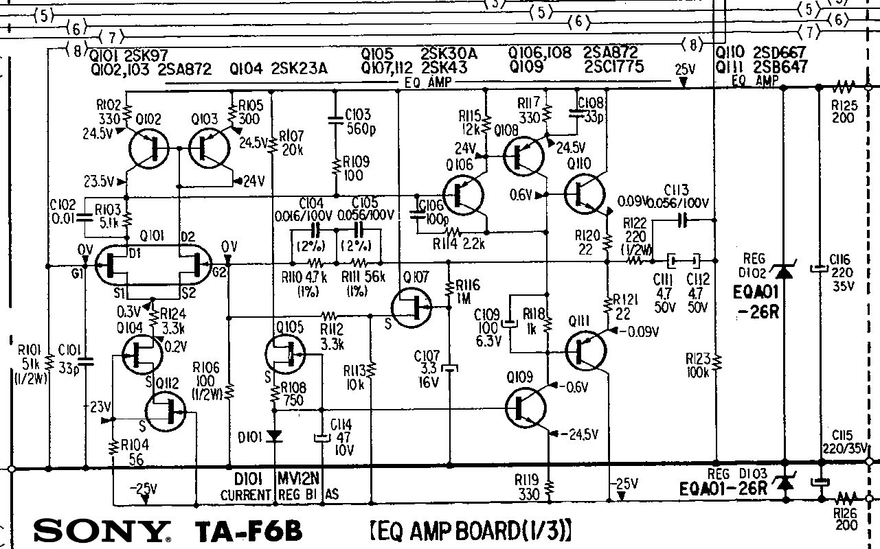
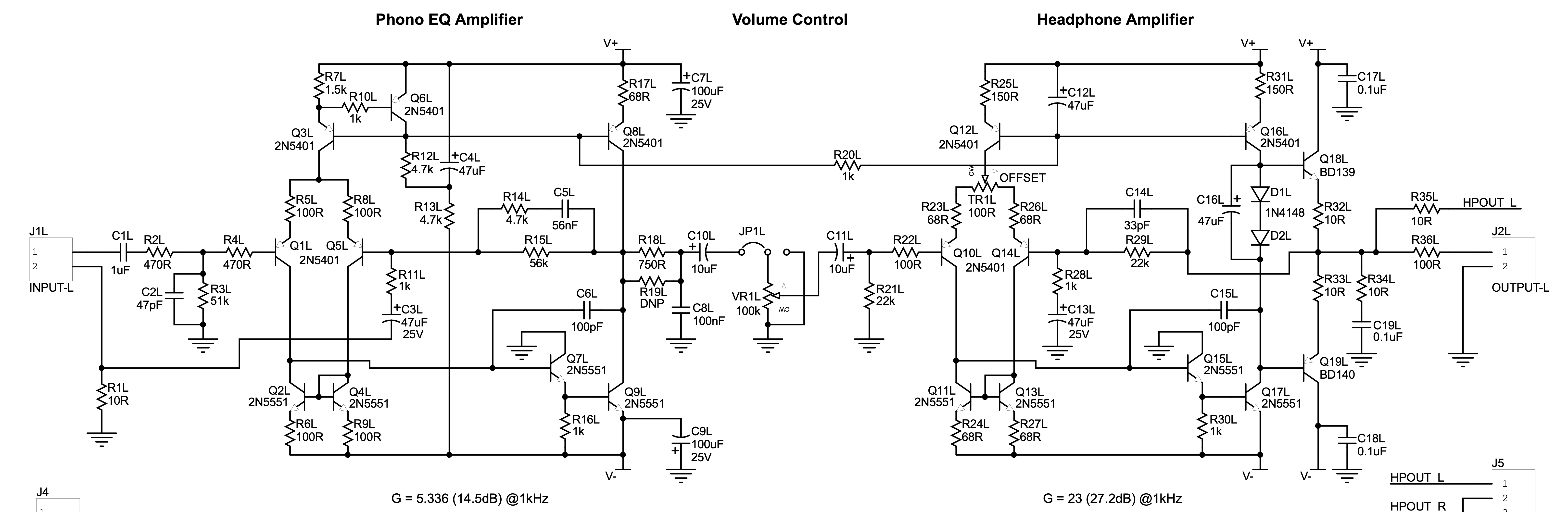
I took the basic concept of using a differential input stage and class-A gain stage with constant current source, and put together a prototype.
I also added a headphone amp built into the same board so that I can easily use headphones.
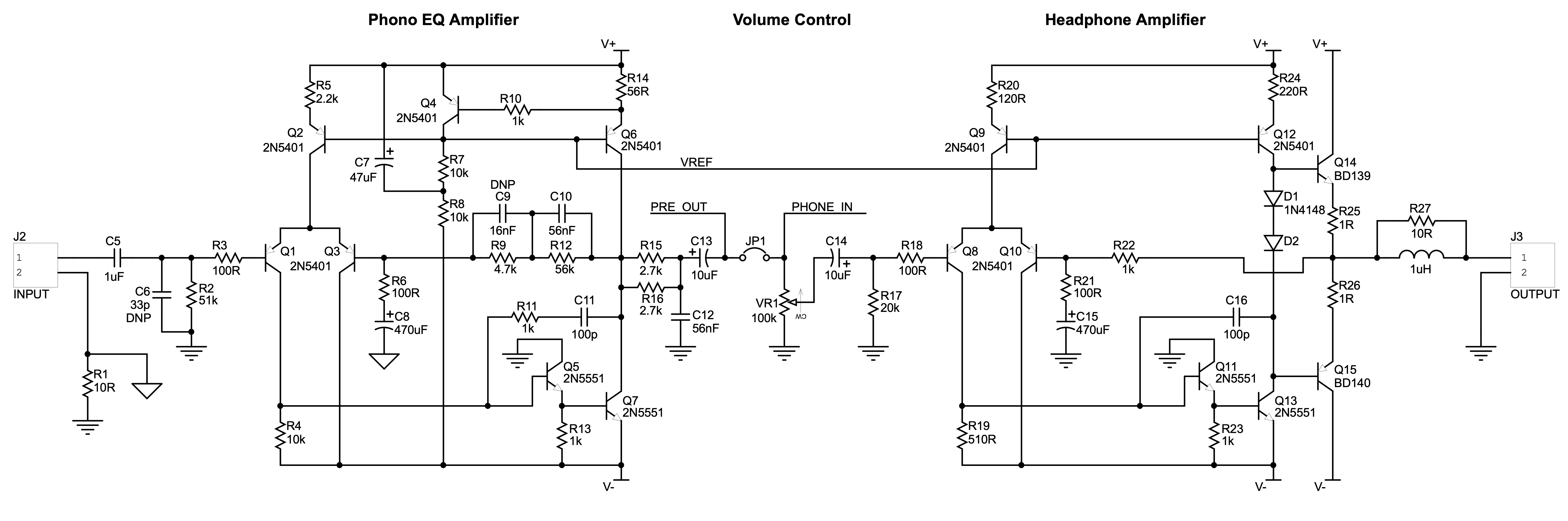 (Only one channel shown)
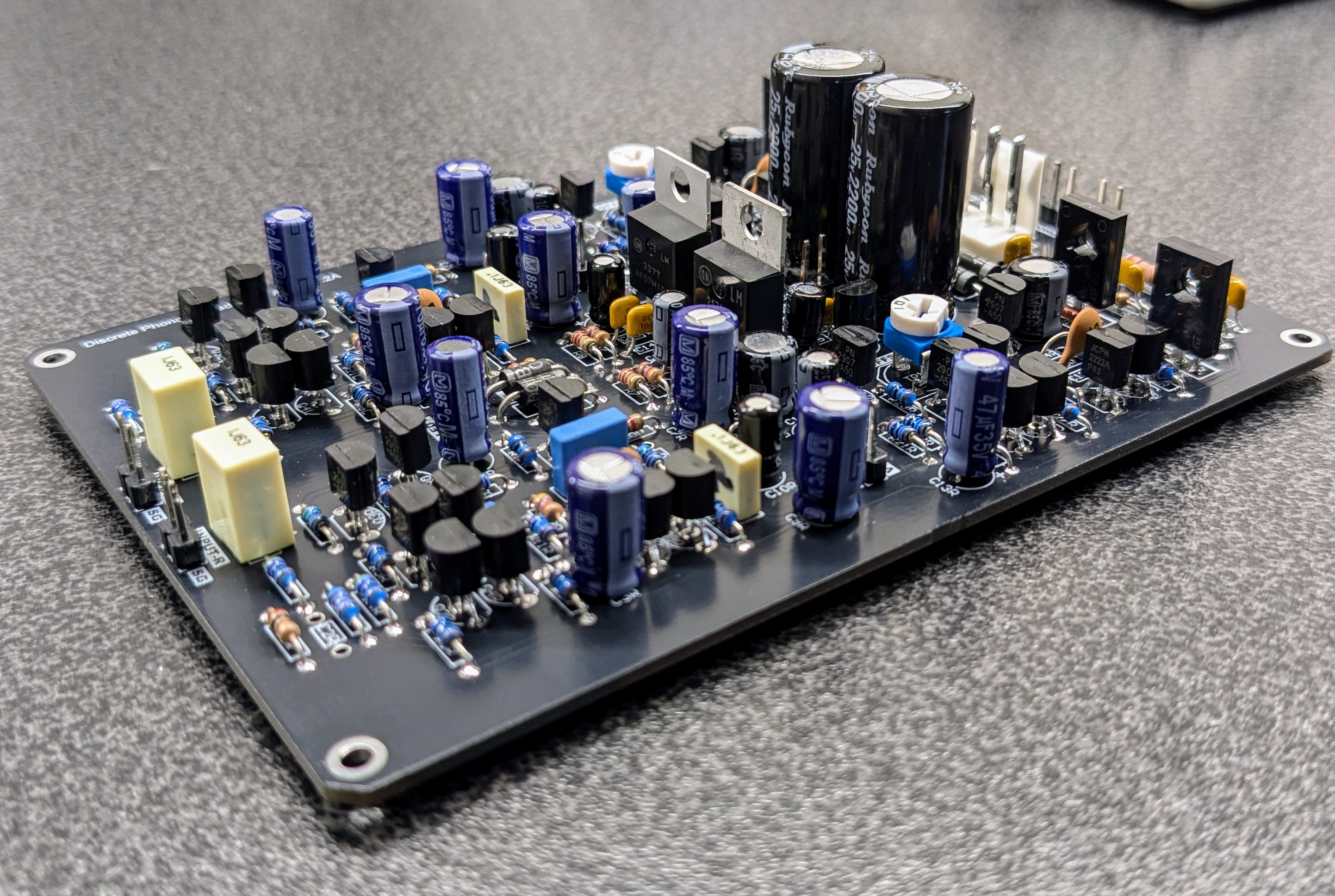
Assembled Rev2 Board
I simply combined parts from different circuits I found everywhere, without much verification.
This prototype managed to produce decent sound (after some tweaking). So I refined the circuit for the 2nd version.
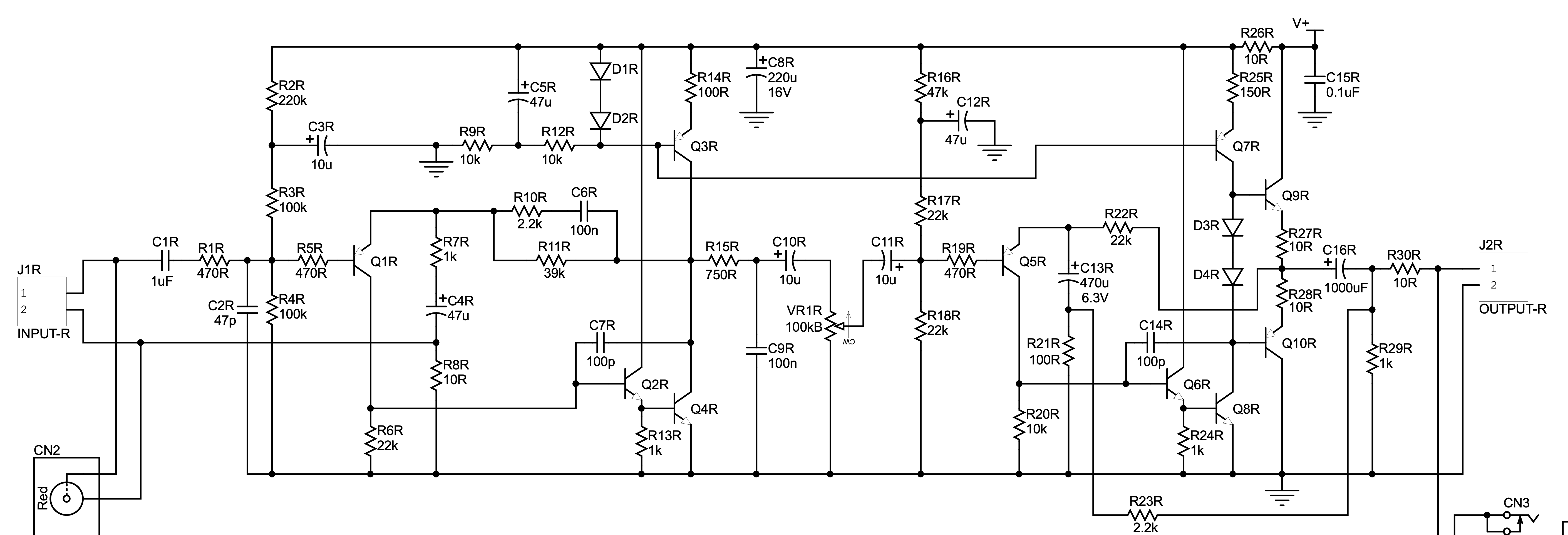
 (Only one channel shown)
I added a current mirror to further enhance the performance. This version produced good sound, but I goofed on the power supply circuit that was incorporated into the same board. The AC current ran too close to the output transistors and produced a faint hum. Although this was only noticeable using a very sensitive pair of headphones, I decided that this board was a failure.
While I was fixing the PCB design, it occurred to me that I should simplify the circuit. Using many transistors to more or less emulate the op-amp seemed pointless.
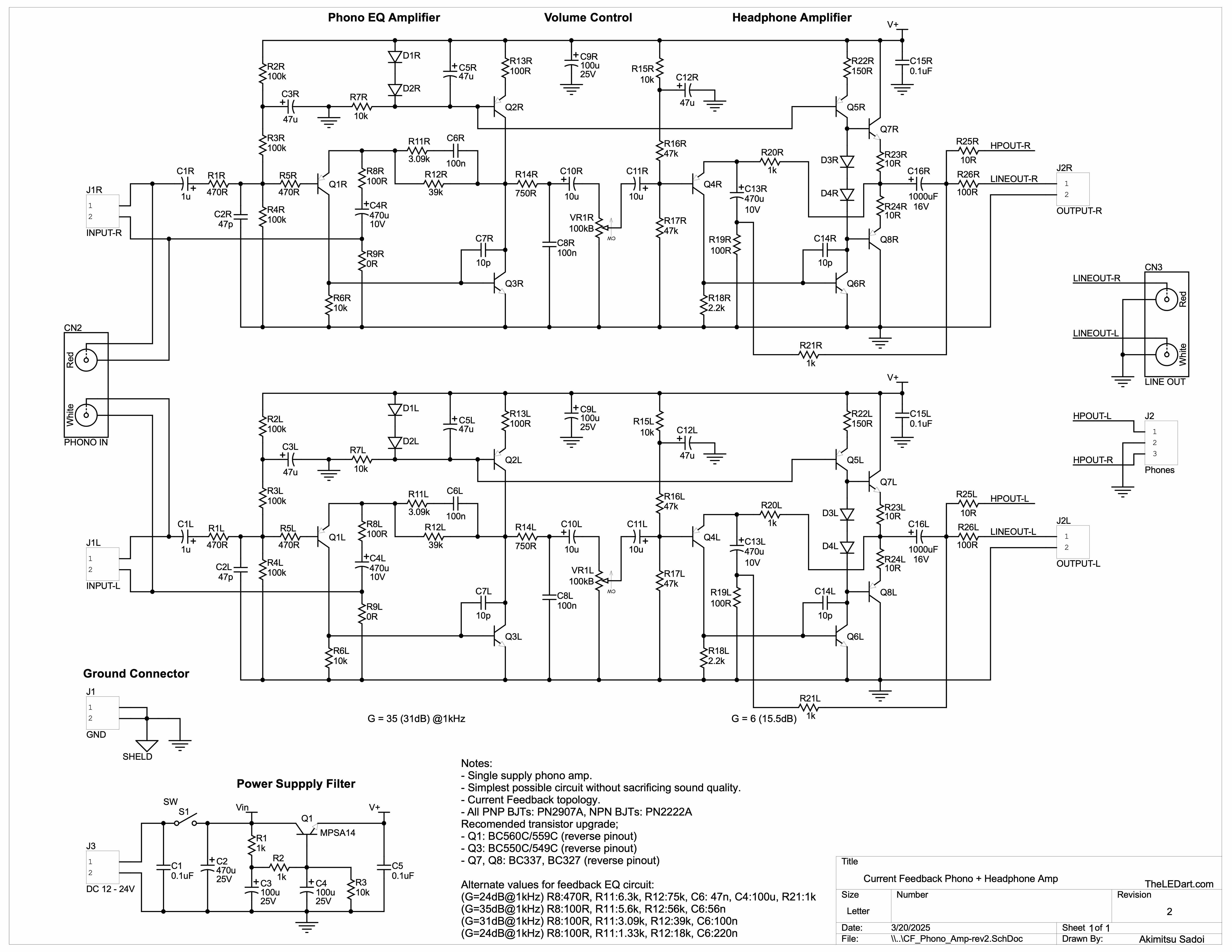
There was a simple amplifier topology that I liked called “current feedback amplifier” (I have made a small power amp using this topology and liked the sound before), so I decided to use it for a phono amp.
 (Only one channel shown)
This simpler circuit produced unexpectedly good sound.
Q2R was included just so that I can experiment with the “beta-enhancer” for the class-A gain stage. I also assembled a second board without it to compare. It turned out that it wasn’t really needed.
After much tweaking of component values and adjusting the gains of each stage, this amplifier started sounding great. Using high-gain, low-noise transistors for the Q1 and Q4 (BC560C and BC550C) made a huge difference especially in very high frequency representation.
One drawback of this (and all single power supply amplifiers) is that they are very sensitive to the power supply noise. I was testing this amp with battery power (which is the best power supply for low noise), but I didn’t want to use battery forever. So I added an active filter circuit to eliminate ripple from the AC adapter that I was going to use. This filter can reduce the ripple voltage to at least -60dB. Upon hearing I simply can not detect any hum on the output.
Here’s the final circuit.
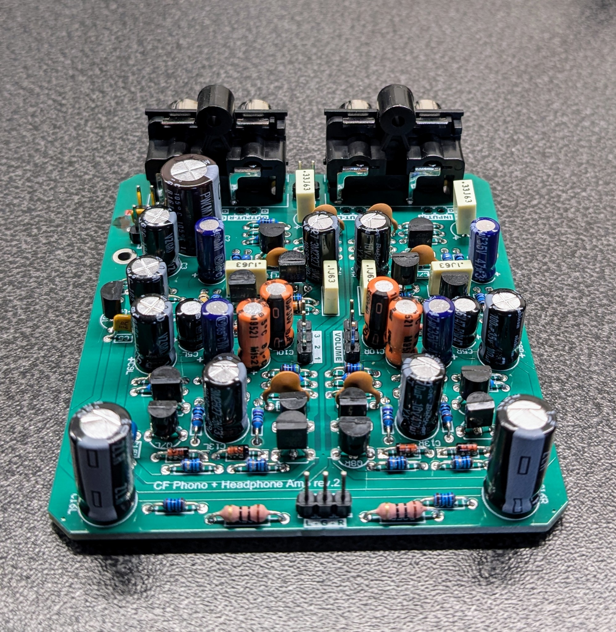
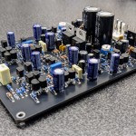
Assembled Current Feedback Phono + Headphone Amp Board
This deceivingly simple circuit produces amazing sound. And it’s more than reasonably low noise.
 Follow
Here’s how I do my SMD PCB assembly
I design a lot of PCBs, and assemble most of them myself. Small quantity PCB fabrication services have become so popular and abundant, I take full advantage of them.
Recently I use PCBWay a lot. Their pricing is close to the lowest (sometimes is the lowest), but the quality is still quite good. My favorite part of their service is that they offer different solder mask colors without extra charge. I don’t like green PCBs so this is a big plus!
For small boards for prototypes, batch based PCB service such as OSHPark still wins, as the shipping cost is much lower than from China. I use OSHPark for boards up to 2 sq inches, and PCBWay for larger.
Oh and PCBWay (and some other Chinese PCB fabs) offer stainless stencil for a very reasonable price. I can usually add one for $10 and it is very nice to receive PCBs and the stencil together.
Here are the photos from my typical PCB assembly using the nice stencil.
Step 1: Gather All Materials
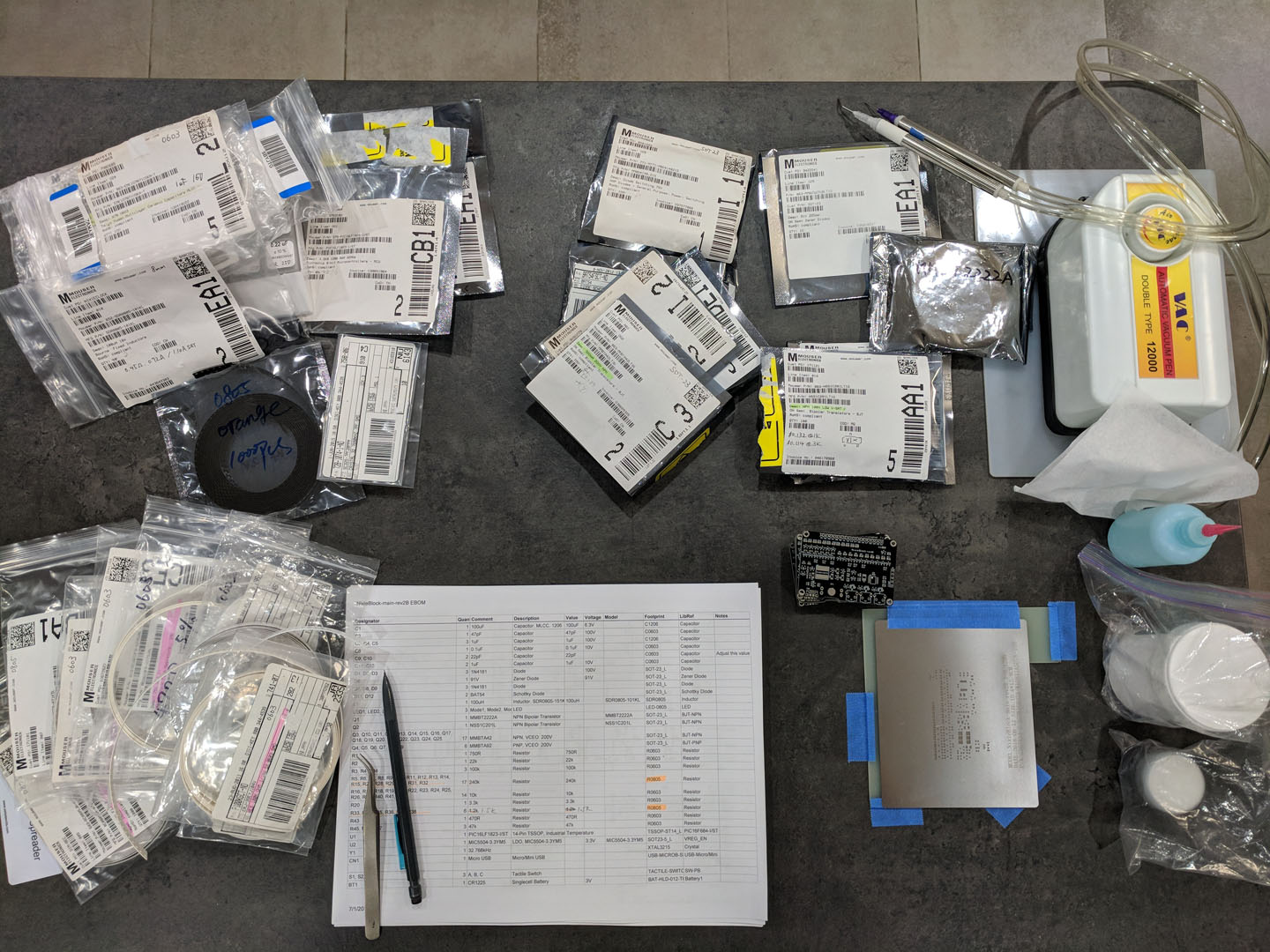
Clear your work area and gather all components, material, and tools. Preparing the organized BOM printed helps to reduce errors.
Step 2: Frame the PCB and align the stencil
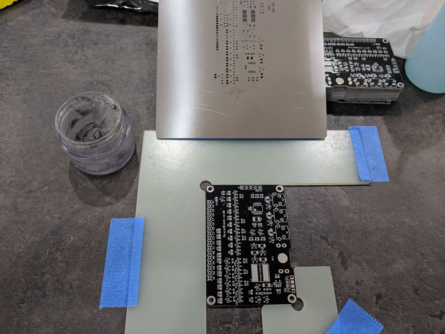
I use squares made of fiberglass to secure the PCB to the desk. Then overlay and align the stencil on top, and secure it with a piece of masking tape.
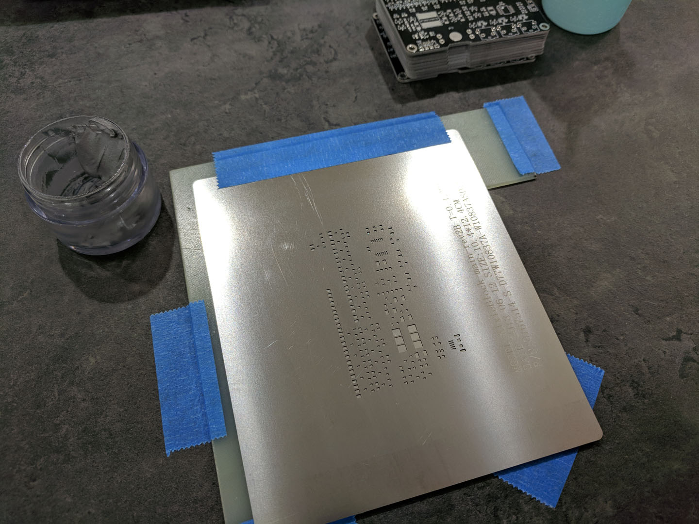
Compared to Polyamide (orange plastic film) stencils, stainless stencils are easier to align to the PCB. The pads kind of “snap” into place.
Step 3: Squeegee time
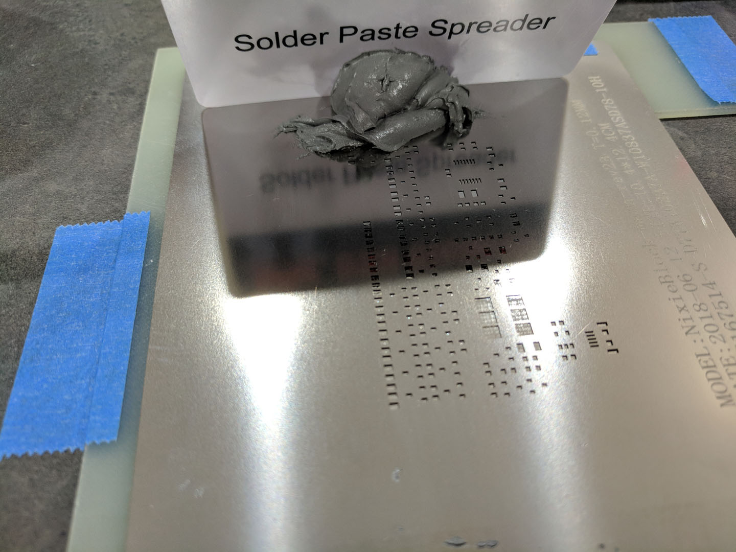
Now it’s time to spread some solder paste onto the PCB. Use plenty of paste and pull the squeegee at a steady speed.
Here the stainless stencil really shines, as the paste spread very smoothly without effort.
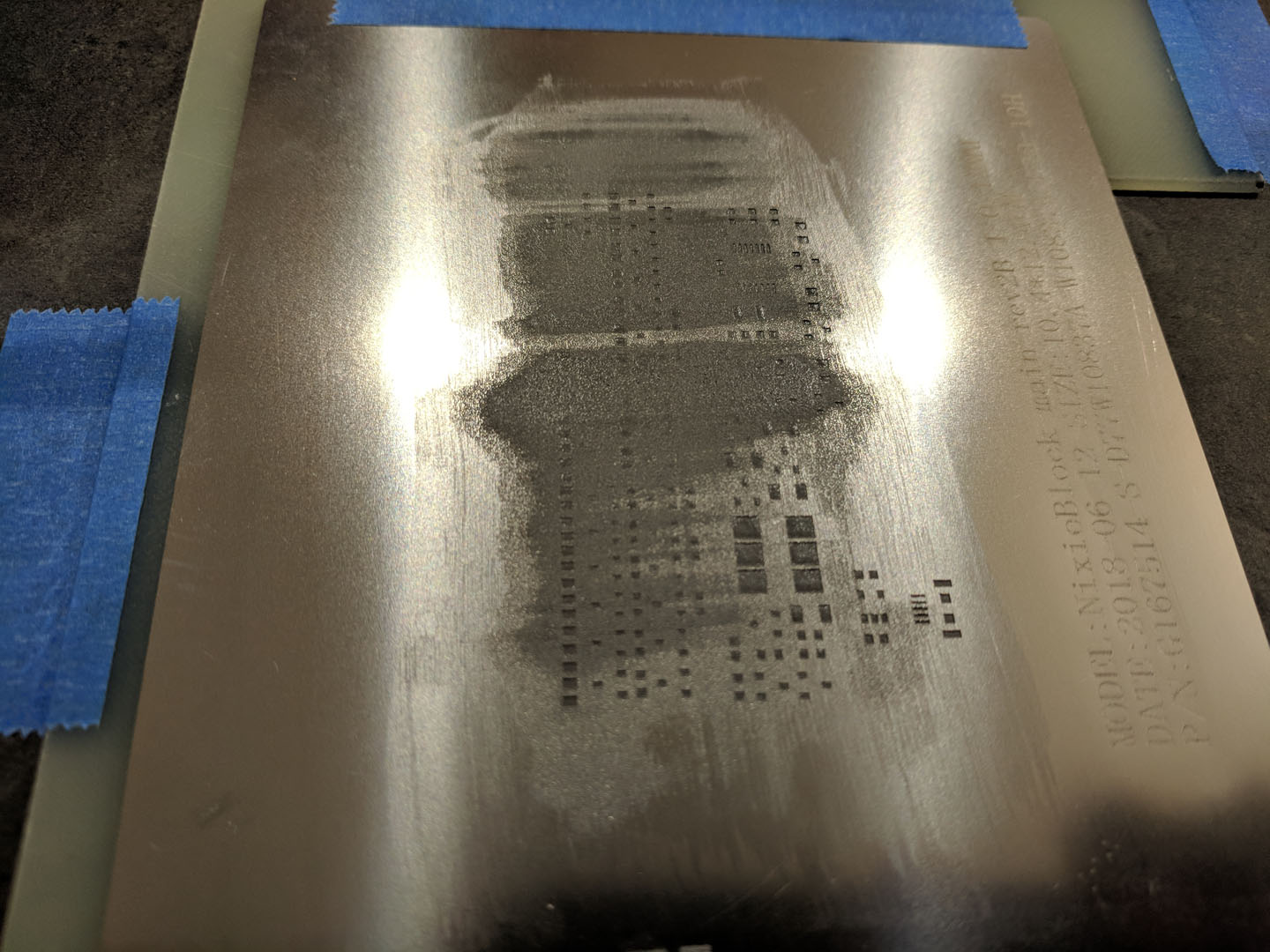
(Ok, I could’ve done a better job, but…)
Step 4: Ready to Pick & Place
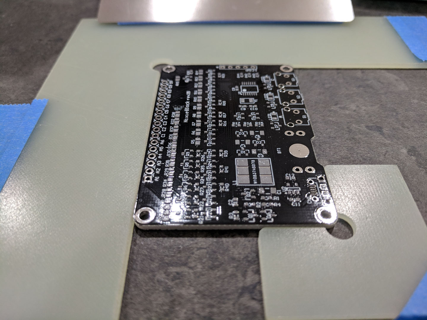
Now the PCB has solder paste beautifully printed on, I’d get busy placing components.
Step 5: Ready to Reflow
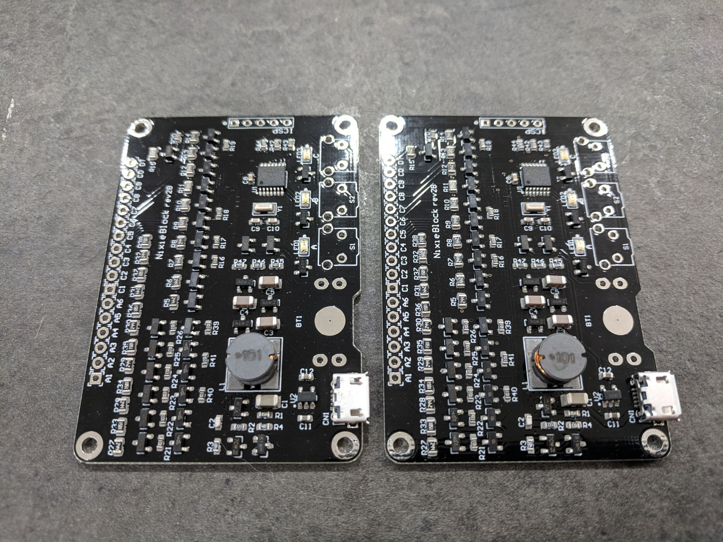
Here the boards have all the components placed and ready to reflow. Sorry I forgot to take photos during the pick & place process.
I use a small reflow oven to reflow PCBs.

Pocket High Voltage Generator Upgrade

HV Generator open output voltage – limited internally to under 200V. The red LED lit up to indicate the voltage limit has reached.
The Pocket High Voltage Generator that I made a few weeks ago proved to be a very handy tool. I have been testing Zener diodes very often since I use many Zeners in 12V to 91V range.
However I wanted to give it a bit more power so that I can test Nixie tubes clearly – the previous design can only give less than 0.5 mA through most Nixie tubes, some digits don’t lit up completely.
I made some upgrades to the components to give it a modest 2 – 5 mA (depending on the voltage) output. While still keeping the same form factor.

Upgraded HV Generator can comfortably drive Nixie tubes at 1 – 2 mA of current.
Now this circuit has enough oomph to shock you if you accidentally touch the output! Not the dangerous level, but it IS shocking. Perhaps one can use this as an electric Jack-in-the-box…
I’m sharing the PCB design of this project. Which can be purchased or downloaded via OSH Park.
![]()

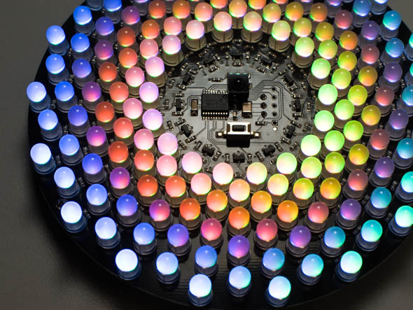
A60 Source Code Published

After receiving many requests, I finally decided to publish/share the firmware source code of A60.
I was put off by the cheap clone made available, but I now think there can be something good in sharing the firmware, so that others might learn something from my code – not that my coding skill is that good, but the way you can use a simple MCU like a PIC24Fxx to directly control the individual brightness of 180 LEDs (60 x (R+G+B)) is pretty cool, because you can same money and space by not using PWM controller ICs.
You can find the code here: https://github.com/theledartist/A60

Pocket High Voltage Generator Quick Build
- There’s an update to this post, including PCB design files. -
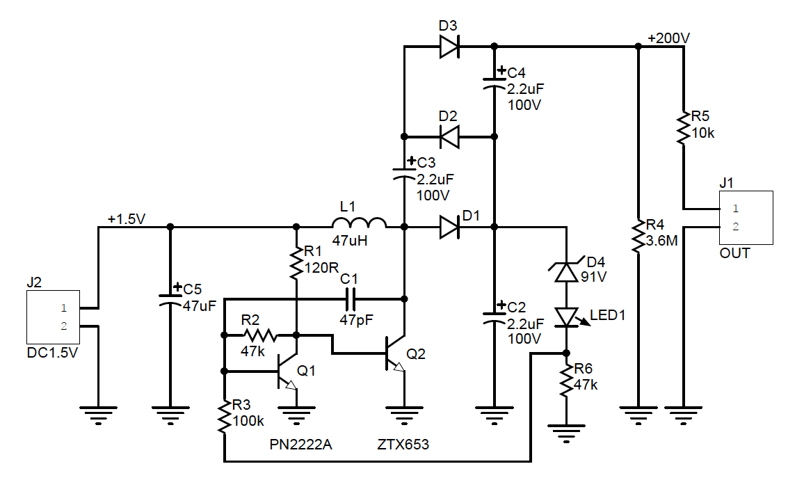
There are times you find yourself looking for a relatively high voltage (100V to 200V often in my case) but low current DC power supply. I have zener diodes that are higher than 30V, which makes the lab supply useless, and filament LEDs with forward voltage over 60V. When I need to test them quickly, I used to hook up a simple rectifier circuit to a variable AC power supply (nothing more than a slidac with isolation transformer). While this gets job done, the setup is capable of supplying much too high current (1A or more), so I was always very nervous and extra careful in handling the circuit. All I need is a little HV generator that gives me around 200V DC and only capable of supplying a milliamp or less. Realizing that I do have such design available – one of the Nixie supply circuit – I just decided to put one together to use.

Pocket HV Generator schematics

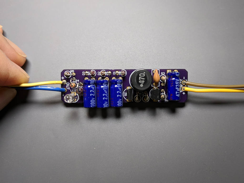
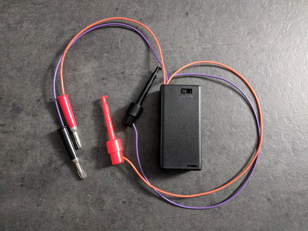
Quick & dirty build of the tool.
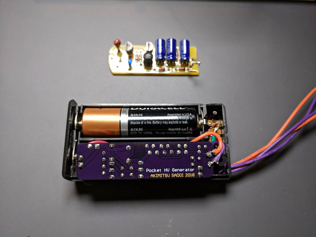
A single AA battery seems to be enough to generate over 200V on the output with no load. But the output quickly lowers when you draw 0.4mA. So it feels pretty safe to handle this casually, and I can only feel a bit of tingling, not electric shock when I touch the output terminals. The tool proved to be quite handy and useful in testing variety of things:
- Zener diodes (zener voltage)
- Switching diodes (reverse breakdown voltage)
- Filament LEDs (forward voltage)
- Regular LEDs (forward voltage – yes it’s ok to use this tool, since it’ll only give less than 1mA even at 2-3V)
- BJTs (breakdown voltages)
- Neon & Nixie tubes (not very bright, but you can tell if one works or not)

Pocket HV Generator testing a zener diode

Pocket HV Generator testing a Nixie tube
This is one of the most useful tools that I’ve made. And it only took a couple of hours to put it together.

Mini Headphone Amp /w Bass Boost

Added a new project to Instructables on headphone amp. This is something that I have made to improve my music listening experience during my subway commute.

Variations on Nixie Power Supply Design
Since I started tinkering with Nixie and other Neon tubes, I found the need for simple (read: inexpensive) high voltage power supply capable of generating over 170V from 5V DC.
After a bit of research I found that most of the high voltage power supply designs use boost converter driven by a PWM controller IC such as MC34063, with a high voltage MOSFET switching an inductor. (Here’s an example of the design.)
Those designs looked a bit overkill to me, so I started designing my own from scratch.
Since I’m familiar with transistor based blocking oscillator circuit to boost voltage (i.e. Joule Thief), I wanted to see if I can use a similar circuit. The switching transistor has to withstand the output voltage of 180V so I picked some high voltage transistors and experimented. Turned out that typical high voltage transistors (C-E breakdown of more than 200V) were too wimpy for the purpose, and the simple two transistor circuit that I was using was not capable of very high duty cycle demanded by high input/output voltage ratio (over 90%).
One way to reduce requirement for the boost converter is to add voltage multiplier at the output. I added a 3 stage voltage multiplier to a circuit using pretty ordinary (inexpensive) transistors. This circuit was able to provide required voltage (about 170V) and up to around 3 to 4mA of driving current to medium sized Nixie like IN-12.
After building a couple of prototype Nixie clocks using this circuit, I found a very nice transistor capable of handling 100V and 1A current.
With this new transistor, I can now reduce the voltage multiplier stage to only one, since the boost circuit itself can produce up to 100V (ok, with safety margin, more like 90V). This circuit outperformed the prior version, producing about 8mA at 170V.

Super simple HVPS using only two transistors. 180V output capable.

Simple two transistor HVPS on a Nixie clock controller PCBA. (Inside yellow rectangle – fits in 12mm x 32mm)
While I was happy with this design – especially the size and cost – and built a couple of Nixie clocks and IN-13 Neon indicator tube projects with it, I still wanted to make it better (mostly wanted more power).
If I can find a transistor capable of withstanding over 200V with a reasonably low loss, I can forgo the voltage multiplier. However the only options that I can find were MOSFETs.
After checking the prices of high voltage MOSFETs such as IRF740, I concluded that it can be more cost effective if I can make it work, since I’ll be removing two diodes and capacitors from the voltage multiplier.
After a bit of experimentation, I got it to work! Here’s the MOSFET based circuit. Note that this design needs at least 9V of input voltage to work (due to the MOSFETs gate voltage). So for the 5V powered projects, I’d still use BJT based design.

Super simple HVPS using only two transistors. 240V output capable with 12V input.
This MOSFET based design is capable of delivering at least 50mA at 200V.

Nixie Clocks – Early Designs

I got my first Nixie tubes in early 2016 and started experimenting. I didn’t know anything about then at the time, but quickly realized that they were pretty simple devices to use.
Only part that needed developing was the high voltage power supply. I did not want to use mains AC as the power source, and ideally wanted to use 5V DC so that the clock can be powered from USB.
After a bit of research I found that most of the high voltage power supply designs use boost converter driven by a PWM controller IC such as MC34063. A large MOSFET switching a good size inductor. Those designs looked a bit overkill to me, so I started designing my own from scratch.
Since I’m familiar with transistor based blocking oscillator circuit to boost voltage, I wanted to see if I can use similar circuit. The switching transistor has to withstand the output voltage of 180V so I picked some high voltage transistors and experimented. Turned out that typical high voltage transistors (C-E breakdown of more than 200V) were too wimpy for the purpose, and the simple two transistor circuit that I was using was not capable of very high duty cycle demanded by high input/output voltage ratio (I’d estimate close to 99%).
One way to reduce requirement for the boost converter is to add voltage multiplier at the output. I added a 3 stage Cockcroft–Walton multiplier to a circuit using pretty ordinary (inexpensive) transistors. This circuit was able to provide required voltage and up to around 3 to 4 mA of driving current to medium sized Nixie like IN-12.
While this power supply was not quite powerful enough for larger Nixie tubes, I went ahead and designed a clock circuit to get my feet wet.
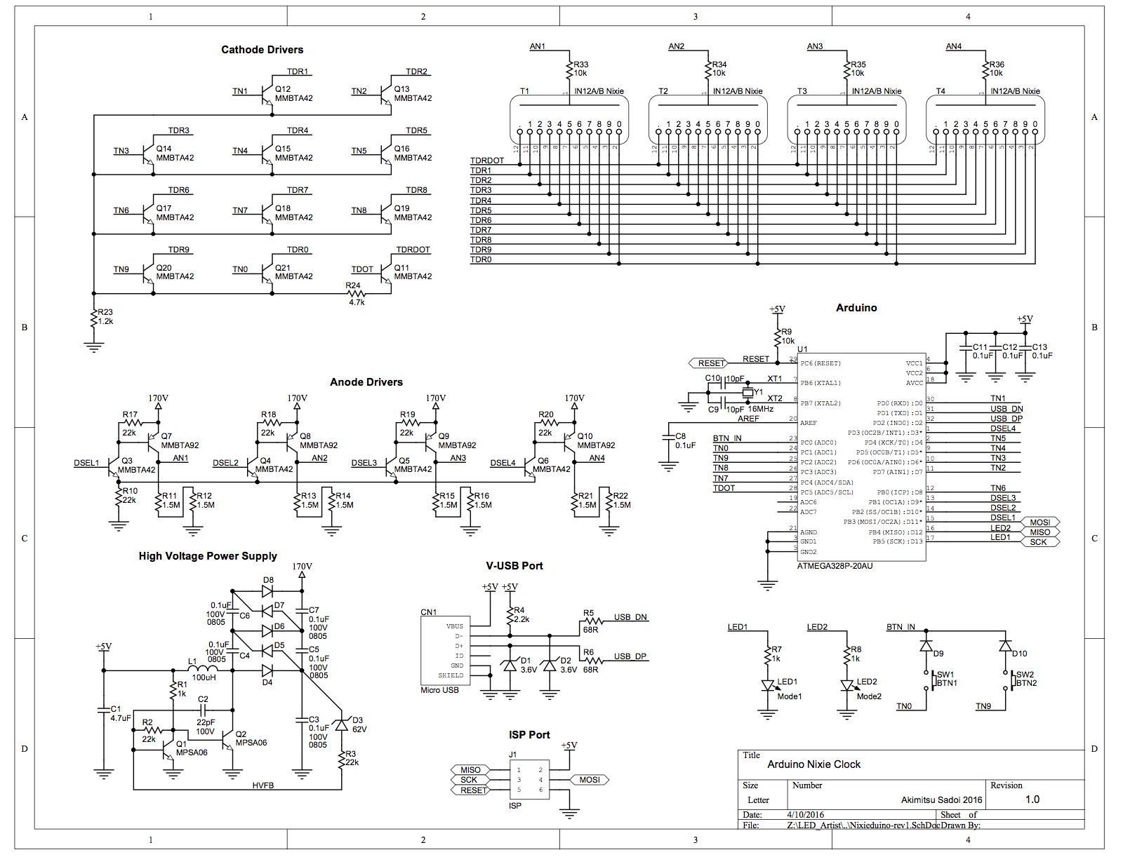
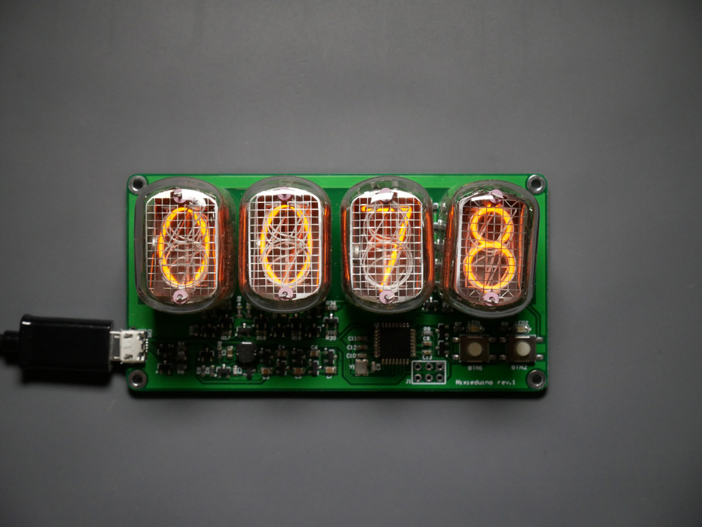
First design was a 4 digit clock using ATMEGA328 – I wanted to make the software easy to develop, so I loaded Arduino boot-loader. I also wanted to use the clock as a multipurpose numerical display so I added a V-USB port.
This prototype had some stupid bugs, but the basic functions such as multiplexing worked. I made a revision of this prototype right after.
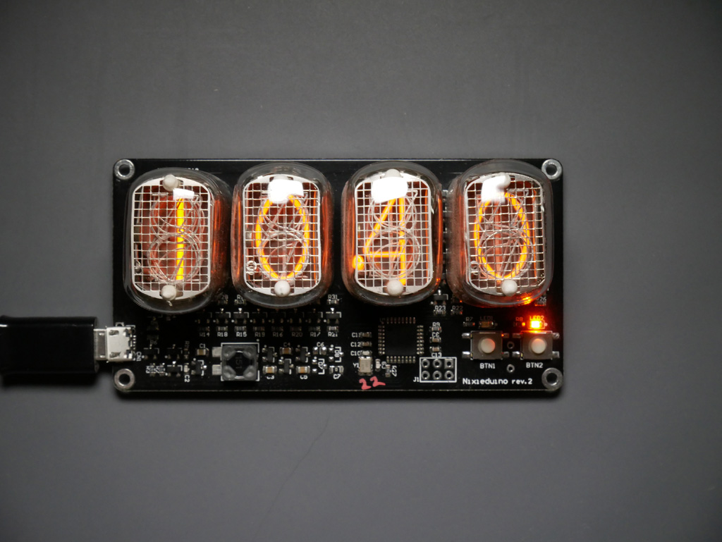
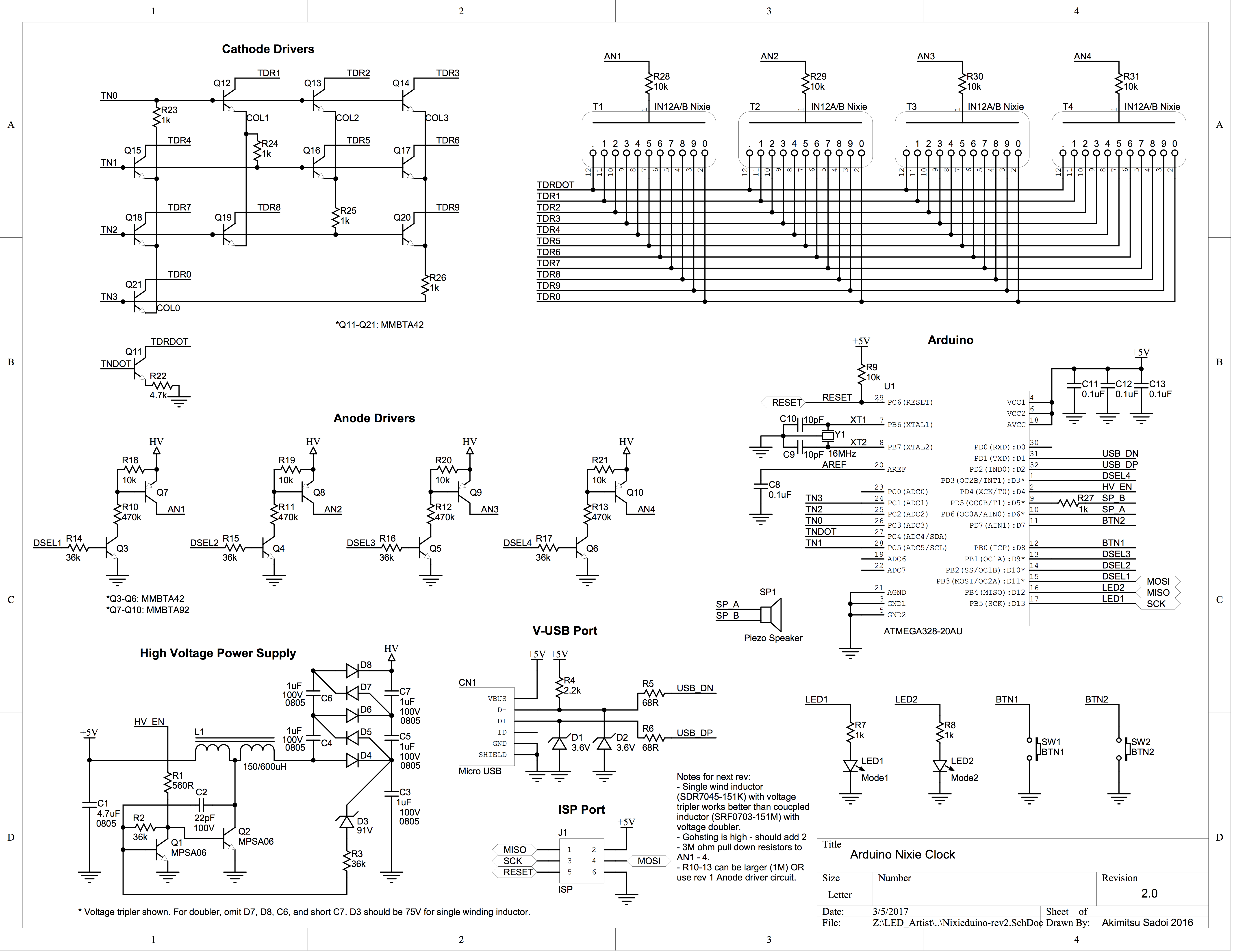
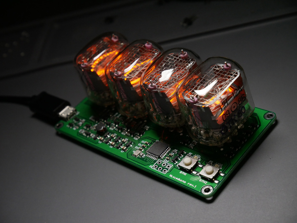
Here I experimented with a tapped inductor to effectively double the boost converter output voltage and do away with voltage doubler instead of tripler.

Are Nixie Tubes cool again?
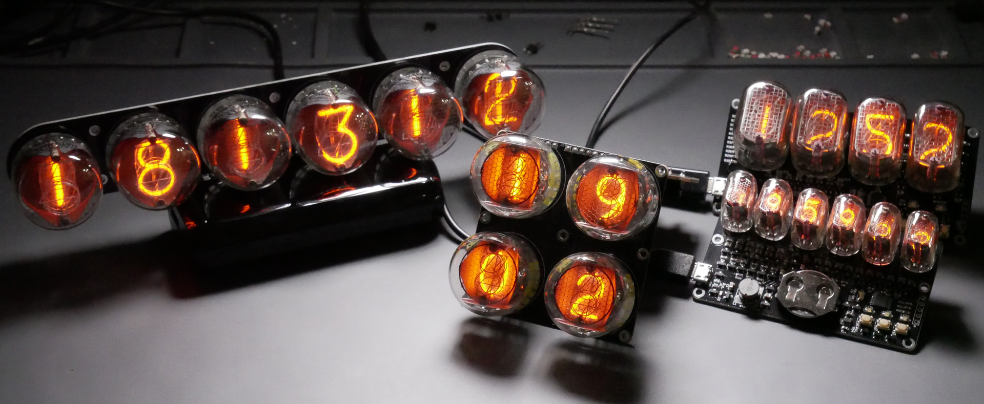

I’ve been playing/designing with Nixie tubes for some time now. I found Nixies very fascinating as the numbers inside them glow just magically.
There are many Nixie Clock designs available on the net. They are usually two types; AC main powered clock without MCUs, or low voltage DC powered with MCUs. I prefer low voltage variety because of the safety reasons, as I like exposed PCBAs.
All of the low voltage designs have some kind of high voltage (180V typical) generation circuit – and I noticed that all of the designs that I see use a pretty hefty MOSFET driven by a PWM controller IC. Somewhat complex and not so small. I kept thinking – there has to be a simpler solution.
I’m sure many people reading this are familiar with Joule Thief circuit. It’s a simple blocking oscillator based boost converter. I have done some work with two transistor variation of Joule Thief extensively, and thought I should be able to use that circuit for Nixie power supply.
Looking at the basic circuit I realize that the output voltage is limited by the breakdown voltage (Vceo) of the switching transistor. So I tried testing with high voltage capable transistors. The result was not so good – you can get the voltage, but could not deliver the current Nixies needed.
So I decided to add voltage doubler to the circuit, which looked promising. After many tries with different transistors and voltage doubler or tripler combinations I was able to come up with a supply that can deliver about 7mA of driving current into a medium sized Nixie. The circuit only uses two transistors, a not so big inductor and a few diodes and capacitors. It is much simpler and smaller than all of the Nixie power supply I have come across.
It’s not as strong (only 180V and 7mA driving current as opposed to 200+V with 10+mA) and voltage regulation is not so good. However it’s more than good enough for small to medium sized Nixie tubes. It can also work with input voltage as low as 2.4V when you don’t need much output current (i.e. miniature Nixies like IN-17).
I have designed a couple of Nixie clocks using this power supply. I will follow up with some descriptions of each stage of the designs.

Aurora 18×18 built into a game kiosk
Build a Rainbow by Moey inc. from Andrew Sahlstrom on Vimeo.
You can see & play the game at Gulliver’s Gate in NYC.

See me at the Maker Faire Bay Area 2014
It’s that time of the year again. I’ve been working tirelessly preparing for Maker Faire Bay Area.
There will be a couple of new products introduced and on sale at special introductory prices!


R48 Battery Life Improved

After looking through the firmware very closely, I figured out a way to reduce power consumption of R48 via firmware tweaking. (Aggressive use of CPU “idle” mode while waiting for PWM pulse to output, etc.)
I managed to reduce the power consumption up to 43%. In my tests the batteries are lasting 50% or more longer!
All R48 will be shipped with the new, improved firmware as of today. If you already have R48, please send in for free upgrade.
How to receive the free firmware upgrade
- Please send your R48 to the address below.
The LED Artist
12A Louis PL
FL 2
Brooklyn, NY 11233 USA - Send only the R48 unit, without batteries or chargers.
- We will pay for the return postage. (Please pay for your postage to send in.)
- Make sure to clearly indicate the return address.
- The upgraded R48 will be sent back via USPS First Class mail.
- Enjoy the longer battery life!


More Products Available at Maker Shed


I’m so excited to announce that my wearable items – A12, R48 (all colors), and USB Li-Ion Charger are now available at Maker Shed!
You can find them here.
Maker Shed also sells Color Organ Triple Deluxe II and Colour Night Joule Thief Kit.

The LED Artist wearables at Adafruit
I’m very excited to announce that now some of my LED wearables are sold at Adafruit!
See the “New Products” video – my wearables are on at 13:35.
R48 Now Available in 4 Colors

R48 wearable LED accessory is now (finally!) available with 4 different color LEDs. In addition to blue, red, green and white LED versions are now available.
Thank you so much for waiting.

Limited Supply – Color Organ Acrylic Case

I have a limited supply of laser-cut acrylic case for Color Organ Triple Deluxe II available. This is one time offer, the cases won’t be available again once the supply is gone.
(The case kit does not include the knob.)

T962A Reflow Oven Hack Instructables

Recently purchased T962A reflow oven. There were a couple of issues that I dealt with. Please see the Instructable on what I did.

See You at the Maker Faire Bay Area
![]()
Hello West Coast! I will be exhibiting at the Maker Faire Bay Area on May 18 & 19th.
This is the largest of Maker Faire, so I will be bringing a lot of stuff, some of which are not yet seen by anyone. (yes I’ve been working hard)
Please come see me and hundreds of great makers at this event. It will be exciting!
Laser Cut Enclosure for Color Organ Triple Deluxe II
I made a laser cut acrylic enclosure for Color Organ Triple Deluxe II.

It’s a very simple design, but very functional. Built with laser cut acrylic and screws and nuts only. No filing, glueing or bending.
You can download the design file, and laser cut 3mm acrylic. I used Ponoko, but you should be able to use any services available.
Use my design as is, or customize as you like.
You will also need four 1 inch, #2-56 machine screws and nuts, such as these.
ColorOrganTripleDx2Enc-rev2.eps
* The design file is formatted according to Ponoko’s specifications. You might have to modify it if you are using a different service.
Through-hole only version of Audio Interface
The through-hole only version of Audio Interface is now available for Aurora 12 bar, Aurora 9×18 mk2 and Aurora 18×18.
Now those who are not into surface mount soldering can build Aurora color organ (or VU meter)!
The circuit is exactly the same as the original surface mount version of Audio Interface.

You can watch the video here.
The interface goes between the power cable and Aurora, using Molex 3 pin connectors. The interface has a 3.5mm stereo audio jack, so you can connect any audio output. There’s a potentiometer to adjust the sensitivity level as well.
Aurora 12 bar, Aurora 9×18 mk2 and Aurora 18×18 have audio or “color organ” modes, which you can select by either pushing the on board button or using a remote control (remote not on Aurora 12 bar).

International Shipping Fees Reduced
I revised the international shipping fees. The recent changes of postal fees made it very difficult to provide reasonable shipping fees to non-US customers. However I’ve signed up with a bulk mailing service, which made possible to reduce international shipping fees.
You will notice “International Economy” shipping option when you go through the checkout. The orders will be shipped via USPS First Class mail, which is very economical. Please note, however this option does not provide any tracking. If you want tracking and quicker delivery, please consider “International Express Air”. “International Priority Air” is quicker than Economy, but still doesn’t provide tracking…
Shipping Delay
Due to Hurricane Sandy, we are experiencing shipping delays. Our area did not get much damage, but postal service is not working.
I think everything will go back to normal in a couple of days.
*** UPDATE: We are back to normal. USPS is reporting normal delivery. ***
Wave JT Firmware Update
A new function has been added to Wave JT. It’s auto-changer or “demo” mode. With this mode activated, Wave JT will change the animation pattern every minute. (Hence the word demo.)
You can activate this new function by holding the button down at the startup (when power is off). After each of eight LEDs has lit once, all LEDs will blink eight times. If you release the button within this period, the demo mode will be activated.
Wave JT only keeps this setting until powered down, so to get out of demo mode, turn off the power, and tap on the button again to turn on the unit.
The kits are now being shipped with this new firmware.